Thermal Paint
 www.thermalpaintservices.com
Thermal Paint
Introduction
Thermal Paints are coating based products that are temperature sensitive. When applied correctly, they create irreversible visual pictures of surface temperature contour patterns. This is an essential tool for the accurate analysis of high temperature materials working close to their maximum temperature capabilities.
Thermal Paint Services, Inc. is a technical expert in this field and has over 30 years of real world test experience with this product. The company has invested many years of development in paint application techniques, color contour analysis, incorporation of new technologies to help in the data gathering and extrapolation and in the presentation and remote management of test cells and data.
The performance of a gas turbine engine is significantly influenced by turbine inlet temperature. Higher turbine inlet temperatures give high cycle efficiency but at the cost of raising the component metal temperature. The allowable component metal temperatures should not exceed 1700-1900 F (927-1038 C) even for the most advanced alloy to avoid failures. Hence, accurate measurement of metal temperatures of the components is essential for component designers so that they can produce reliable and durable engines.
A heat transfer engineer would have a wealth of useful data if a permanent record of actual hardware temperatures in an operating gas turbine could be made. However, measuring actual temperatures of rotating components such as turbine blades using thermocouples through slip ring tests has been expensive and difficult at best. In any case, only spot temperatures can be recorded. Similarly, high frequency pyrometer techniques only give spot temperatures of components on which a pyrometer probe can be aimed. Temperatures indicating thermal paints offer a permanent, simple and relatively inexpensive way to overcome this problem for both stationary and rotating components.
Although thermal paints have been used in turbomachinery design for a long period of time, the results have often been discouraging due to subjective interpretation of paint colors, sensitivity to the environment, and inaccuracy of the predictions. Recent improvements in the application process, gas turbine test procedure, and color interpretation technique have led to the solution of these past problems.
Thermal Paint Uses and Advantages
The cost of a thermal paint test compared to a slip ring test is about 30%. By using thermal paints, the test and analysis time can be reduced by a factor of 3 compared to a conventional test. This combination of saving cost and test & analysis time reduces the development cost of a gas turbine manufacturer many folds giving him an edge over competition. The other obvious cost saving using thermal paints is that the painted parts can be cleaned and reused after a test, whereas experience has shown that in a conventional test with thermocouples, many very expensive Pt/Rh thermocouples need to be attached to parts, and after a single test the parts are discarded. Also, thermocouples can affect the aerodynamics and thermodynamics of the test engine which is not the case with thermal paints.
After a test with the painted parts an overall coverage of isotherms and temperature gradients over the entire surface of a component is achieved and any local hot spot on a rotating or stationary part can be easily identified. Any subsequent removal of the local hot spot can be visually confirmed with thermal paints.
The paint color isotherms can be accurate to ±15ºF (±8 ºC) and interpolation between isotherms can give an accurate assessment of the temperature of any point on the component which has been paint tested. The paints are being used with a high degree of accuracy and reliability in the design and testing of combustion and turbine components.
The paints can be used on a variety of surfaces, including metallic, ceramic and plastic, with applications in a range of areas such as:
stages, turbine rotor blades - all stages, turbine rotor wheels, turbine vane cases and engine exhaust cones.
- Heat treatment processes
- Composite cure cycles
- Monitoring stored substances
- Monitoring furnace liner conditions
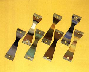
Thermal painting involves the applying of a very thin coat of a selected paint to the required area of a component. Like the liquid crystals, the paint changes to colors in response to specific temperatures. Unlike liquid crystals, the reaction is irreversible and the paint retains the color corresponding to the highest temperature it experienced, making it a permanent record.
The procedure is to paint the parts before an engine is assembled and then simply install the painted parts into the engine during the test-stand build up. (Painted parts can be stored in dry conditions for an indefinite period without any resulting deterioration in performance). After the engine is run for a predetermined period of time, the painted parts are removed and the surface color contours remain as a record of the temperatures the surface experienced.
Interpreting Paint Contours
Skillful interpreting of the thermal paint coloration pattern after a test run involves four major phases:
B. Assigning quantitative values to each isotherm area.
C. Recording the paint pattern, by photographic means.
D. Analysis by the engine designer.
The boundary lines of the paint color contours are sketched by hand by skilled personnel. Alternatively, color digital photographs can be taken and an image manipulating software can be utilized to process color images of paint color contours.
Quantitative values are assigned to each isotherm area by the use of calibrated test coupons. This is the key to the temperature/color relationship.
Any single color in the series can span a 100-200 ºF (38-93ºC) temperature range. So, assigning an exact quantity of temperature may seem a problem, but an exact temperature can be assigned to any transition point between the sequential colors. Also by using different paints with different color bands (i.e. different temperature bands) for the same target surface temperature, it is possible to narrow down an area's temperature to ±30 ˚F (±17ºC). For example: turbine rotor blades which experience the same test temperature due to rotation can be painted with different paints in order to narrow down the temperature represented by the color bands.
The color change depends mainly on the operating temperature, but exposure time to operating temperature also influence the color change. So the parts have to be tested for selected times.
Analysis of the contoured parts by an engine designer often leads to elimination of problem areas or to specific improvements in a previously satisfactory component. Also several configurations of the same component (for example different cooling schemes of a cooled turbine rotor blades) can be paint tested in a single rainbow test to determine the resultant variations in temperature due to different cooling schemes or the best feature of a particular scheme. Cooling effectiveness can be calculated and the turbine rotor entry temperature profile coming from a combustor can also be determined.
TPS Thermal Paints
Multi-Change Paints
|
Paint Name
|
Temperature range
|
|
| oF | oC | |
| KN1 | 320-446 | 160-230 |
| KN2 | 468-491 | 242-255 |
| KN3 | 914-2282 | 490-1250 |
| KN4 | 219-405 | 104-207 |
| KN5 | 307-1922 | 153-1050 |
| KN6 | 302-2139 | 150-1170 |
| KN7 | 662-1517 | 350-825 |
| KN8 | 419-1670 | 215-910 |
| KN9 | 215-910 | 232-262 |
| KN10 | 752-1042 | 400-561 |
| KN11 | 275-401 | 135-205 |
| KN12 | 329-473 | 165-245 |
| KN13 | 968-2021 | 520-1105 |
| KN14 | 743-1076 | 395-580 |
| KN15 | 531-2255 | 277-1235 |
KN5 has 10 color changes, KN6 has 12 color changes, KN3 and KN15 have 7 color changes respectively, KN8 has 6 color changes, and the rest of the paints have 2 to 6 color changes.
Single-Change Paints
| Paint Name |
Color Change Temperature
(After Ten Minutes of Heating) |
Initial Paint Color |
Final Color After Ten Minutes Heating |
|
| oF | oC | |||
| CJKN1 | 118 | 48 | Pink | Lavender Blue |
| CJKN2 | 176 | 80 | Pink | Lavender |
| CJKN3 | 311 | 155 | Blue | Dark Green |
| CJKN4* | 367 | 186 | Yellow | Black |
| CJKN5* | 437 | 225 | Yellow | Black/Brown |
| CJKN6 | 464 | 240 | Yellow | Red/Brown |
| CJKN7 | 527 | 275 | Blue/Grey | Lavender |
| CJKN8 | 693 | 367 | Mauve/Red | Grey |
| CJKN9 | 752 | 400 | Mauve | White |
| CJKN10 | 837 | 447 | Green | Salmon Pink |
| CJKN11 | 856 | 458 | Green | White |
| CJKN12 | 1022 | 550 | Orange | Yellow |
| CJKN13 | 1166 | 630 | Red | White |
| (* = Water based paints not suitable for spraying, should be brush applied) | ||||
Thermal Paint Color Analysis Digital System (TPCADS)
The Thermal Paint Color Analysis Digital System (TPCADS) consists of the following parts:
Hardware:
- Lens and lens adapter
- Cameral adjustable rail
- Linear LED lights, with four 36w fluorescent tubes
- Kaiser Stand RSX with Arm RTX, base 20” x 24”
- Computer System with 19" monitor
- Another VGA display
- VGA splitter
- VGA extension cable
Examples of the color analysis software